CP5 Assembly Guide
Damaged or Missing Parts All kits and parts are checked before being shipped to you. If something arrives damaged or if your kit is missing a part, please open a support ticket to inquire about a replacement. Missing parts will be replaced at our expense. Damaged parts should be returned for verification. If the part shows signs of use beyond what was necessary to determine that it was damaged, DIY Recording Equipment, LLC reserves the right not to replace the part.
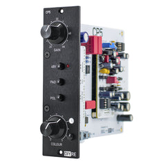
Thank you for purchasing a CP5 Colour Mic Preamp!
If this is your first DIY project ever, we recommend reading our Getting Started Guide.

Required Tools
You'll need the tools below to complete this build.

Soldering Iron
We recommend an adjustable-temperature station, such as the $40 Weller WLC100.

Solder
You can use 60/40 "leaded" solder or lead-free. We recommend 60/40 because it flows better and is easier for beginners to use.
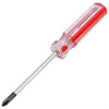
Phillips Head Screwdriver
A #1 Phillips head screwdriver.
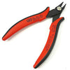
Wire Cutters
You'll need a pair of good "snips" for cutting of the excess leads after soldering.
Optional Tools
These tools aren't strictly necessary but can make your build a bit easier.

Tape
A bit of clear tape will help hold some tricky components in place for soldering.

Multi-Meter
If you find the color bands on resistors a bit hard to read, you can use a meter to sort them with absolute confidence.
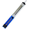
Desoldering Pump
If you accidentally solder something in the wrong place, a desoldering pump can save the day.
0. Resistor Calculator
Type in the value of the resistor you need and this tool will show you the corresponding color code.
Using The Interactive Build Map
We've designed an interactive build map to aid in placing the components on your PCB. You can follow along while placing all the parts, or open it for particular sections as you see fit. To start at a particular section, click link to the build map below that step.
Resistors

Sort Bag 1
Print the CP5 Component Sorting Sheet (PDF) and sort the parts in bags 1 (on page 1). You can identify the resistors by their color code or with a multi-meter.

Bend Resistors
Bend the resistor leads at the body so they can be inserted into the PCB.

Place All Resistors
Place the resistors in their respective places on the PCB.

Bend Resistors Against PCB
Bend the leads of the resistors against the bottom of the PCB so that the resistors stay in place during soldering.

Solder Resistors
Now solder the resistors to the PCB. Observe good soldering technique: heat the pad and lead for 2-3 seconds, apply a small bit of solder, and continue to heat the pad for another 2-3 seconds. Allow each solder joint 10 seconds to cool before moving on to the next one. The finished joints should be shiny and should have just enough solder to cover the pad entirely.

Trim Resistors
Once all of the solder joints have cooled, use your clippers to trim away the excess leads. Your goal should be to clip as close as possible to the joint without clipping the joint itself.
Small Capacitors, Fuses, Diodes, Ferrite Beads
Sort Bag 2
Sort the parts from bag 2 (on page 1 of the Component Sorting Sheet).

Cut Fuses From Tape
Use wire cutters to remove the fuses F1 and F2 from their packaging tape.

Populate Remaining Small Parts
As you did with the resistors, place, bend, solder, and trim the parts in bag 2. Pay close attention to the diodes D1 and D2, which are polarized. Make sure to line up the line on the diodes with the line on the PCB.
Sockets, Diode Bridges

Solder IC Sockets
Place the three 8-pin IC sockets in the U1-U3 positions on the PCB. Make sure to align the notch in the sockets' plastic with that one the PCB. Tape the sockets in place, solder them, then remove the tape.

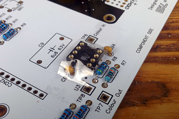
Solder Colour Socket
Flip the PCB over and place the 8-pin Colour socket in the CM1 position.
Now double check: is the socket inserted from the bottom of the PCB? Can you see the big DIYRE logo? Good! Now tape and solder.

Solder Diode Bridges
Place and solder the two diode bridges in the BR1 and BR2 positions. Make sure they are oriented according to the drawing on the PCB before soldering.
Large Capacitors
Quick Question

Populate Large Capacitors
Place, bend, solder, and trim the capacitors from bag 4.
Note that C1, C2, C3, C8, C10, and C11 are polarized, meaning they must be inserted in the PCB in a certain direction. The longer lead is the positive terminal, while the strip on the body corresponds to the negative terminal. Place the capacitors on the PCB, taking extra care to place the longer lead closer to the "+" marking on the PCB.
Pots, Swtiches, Daughter Board Hardware

Populate Mounting Brackets
Flip the PCB over and insert the brackets H1 and H2 from the bottom of the PCB. Solder them, but do not trim the leads.

Tape and Solder LED Board Sockets
Tape and solder the 12-pin sockets to the CON1 and CON2 positions.

Insert LED Board Headers and Standoffs
Insert the 12-pin headers into the sockets and thread the standoffs and two screws into the H3, H4 positions.

Solder Potentiometers
Solder the potentiometers into the VR1 and VR2 postions and clip the excess leads.

Place Switches
Place the switches on the smaller LED PCB. Note that three of the switches are inserted from the bottom of the PCB, while the Colour switch is inserted from the top. Make sure that the front of the switches are pointed out, toward where the front panel will be.

Bend Switch Leads
Use a screw driver to bend two leads of each switch against the bottom of the PCB to hold them in place.

Solder and Trim Switches
Solder the switches and trim the excess leads. Now screw the LED board onto the standoffs, making sure to seat the 12-pin headers in the CON3 and CON4 positions.

Place Switch Caps
Press the caps onto the switches.

Solder Headers
Solder the 12-pin headers to the LED PCB.
LEDs, Front Panel Hardware

Attach Front Panel
Fasten the front panel to the PCB assembly by screwing the hex-drive screws into the H1 and H2 brackets. Press the LED lens through the Colour indicator hole on the front panel.
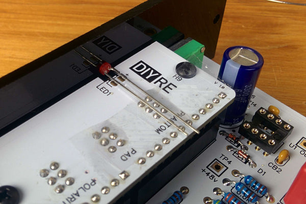
Place +48 LED
Place the red LED through the front panel over the LED1 pads. The longer lead of the LED indicates the positive terminal. Make sure to place this lead over the "+" pad. Once you've double checked it's orientation, tape the LED in place.

Solder +48 LED
Solder the LED in place by heating the pad and lead at the same time while applying a generous amount of solder.

Trim +48 LED
Trim away the excess leads of the LED and remove the tape.

Insert Colour LED
Spread the leads of the Colour LED so they will fit in the LED2 holes. On this LED, the long lead indicates the negative terminal. Insert this terminal into the "-" pad.

Press Colour LED
Press the Colour LED down until it makes contact with the motherboard PCB. This, it turns out, is the perfect place to bend the leads.

Bend Colour LED
Bend the LED towards the front panel until it sits flat against the LED PCB.

Solder Colour LED
Solder the Colour LED from the top of the LED PCB.

Trim Colour LED Leads
Trim the LED's leads from the bottom of the LED PCB.
Integrated Circuits
Sort Bag 7
Sort the parts from bag 7 (on page 3 of the Component Sorting Sheet).
![]() Bag 7 on Interactive Build Map
Bag 7 on Interactive Build Map
Note kits now include DRV134 instead of THAT 1646.

Bend IC Leads
See how the pins of the ICs protrude from the body at slightly wider than a 90 degree angle? In order to fit the IC into the socket, we'll need to bend the leads inward a bit. Set each IC on its side and press from the other side to bend all the leads at once. Then flip the IC over and do the same for the other side. When you are done the leads should be perpendicular to the body.

Place ICs
Insert the ICs U1-U3 into their respective sockets. Set the IC on top of the socket, making sure to align the semi-circular notches. Some NE5532s have a dot instead of a notch; in this case align the side with the dot with the notch on the IC socket. Double check this! Now apply pressure with one or two fingers to press the IC firmly into the socket. The IC positions are:
U1 = THAT 1512
U2 = NE5532
U3 = THAT1646 or DRV134

Attach Knobs
Fasten the washers and nuts to the knobs. Turn all of the pot shafts to the 12 o'clock position (10 detents from full CW or CCW). Now place the knob over the shaft so that the white indicator line points to the middle of the top position. Then fasten the knob with the included hex wrench.
Final Checks
Before you wrap up, check the following things:
-
Capacitor orientation: Is the stripe on the cap on the opposite side from the "+" marking on the PCB?
-
IC orientation: Does the dot/notch on the IC align with the notches on the socket and PCB?
-
Diode orientation: Do the stripes on the diode match those on the PCB?
-
Resistors: Do all of the resistor positions correspond the chart and/or sorting sheet?
-
Soldering: Is every solder joint shiny and clean? If one is cloudy or misshapen, try reheating it for 8 seconds and adding a tiny bit more solder.
-
Trimming: Are all of the excess leads trimmed down as close to the joint as possible?
All good? Congrats on finishing your build! Have a question or problem? Drop us a line.
Help Us Improve
1
2
3
4
5
6
7
8
9
10